Introduction
The Serial library can be used to communicate between Arduino(s) and computers over a USB cable (wired) or** Bluetooth/Zigbee (wireless). **This inbuilt library contains built-in functions for the same. In fact, it is used implicitly when we upload sketches/programs to the Arduino.
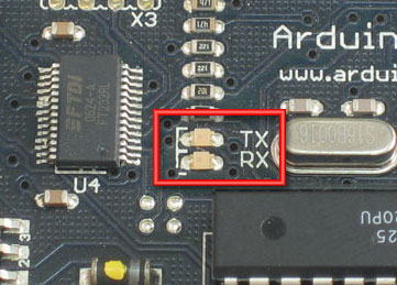
There are two data lines in serial communication, RX and TX, stand for receiver and transmitter. A communication wire, e.g. USB typically connects the RX pin of the Arduino to the TX pin of the computer; and the TX pin of the Arduino to the RX pin of the computer. The board has a couple of LEDs which light up when data is being received / transmitted.

Basic Communication
If you face issues while uploading the code, make sure that pins 0 and 1 of the Arduino are not connected to anything, since they double up as RX and TX pins.
The **Serial.begin() **function starts off the communication channel. The 9600 parameter is the data rate in bits per second, which must be the same for both the receiver and the sender.
The Serial.println() function takes in a string or variable and transmits it, followed by a new line.
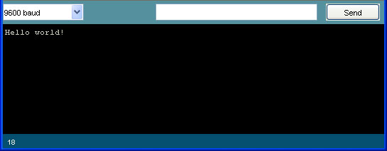
Upload the sketch on the board, and press Ctrl+Shift+M to bring up the Serial monitor.

The monitor displays all incoming data from the board, as well as allows sending data to it. The** Serial.read() **function returns the last received character by the Arduino, and is illustrated in the next example.
Another useful function is Serial.available() which returns true at the moment the Arduino receives data. It can be used effectively inside a loop to check for incoming commands.
Remote Controlled Car
Now for some fun and arguably the most obvious use of communication: controlling a remote controlled car!
You can connect a couple of motors to a base to form a differential drive. Hook them up to a motor driver circuit (as illustrated in the H-bridge section of our Line Follower tutorial and our circuit schematics repository)
The motor driver / H-bridge circuit takes 4 inputs which can be used to control forward, backward, left and right motion of the robot.
Running this code, when the board sends the motor proper directions according to the command w/s/a/d issued by the keyboard in the monitor. ‘o’ stops the bot and the rest of the keys are invalid for our purposes
Moving on to Wireless
So far, we have controlled our robot through a USB cable. We can extend this into a wireless solution using the following communication methods:
- Radio Frequency Modules
- Bluetooth Modules
- ZigBee / Xbee Module